Five-axis scan heads offer a fast, flexible way to produce precise holes, contoured slots and other features with fully defined cross sections. With an appropriate system, control of the laser, scanner and workpiece positioning can extend across the complete micromachining operation and support parts with submicrometre dimensional tolerances.
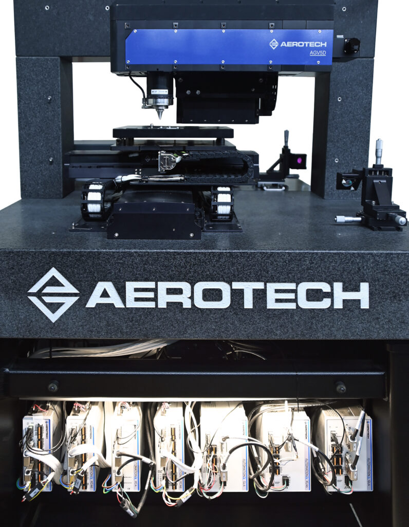
The example described here combines Aerotech’s AGV5D five-axis laser scanner with precision linear-motion axes and a control system. It explains the operating principle and G-code programming approach, using standard CAM software and built-in motion functions for complex micrometre-scale drilling and milling.
How the five-axis laser-motion system works
Understanding the benefits of five-axis microdrilling and milling, and how their precision is quantified, requires an understanding of the example system’s operation and programming.
The AGV5D manipulates the beam in five degrees of freedom:
X and Y position the spot within the field at a selected Z height, providing two degrees of freedom.
Z controls the focal position along the depth axis.
A controls the beam’s cone angle or tilt relative to Z.
C controls the beam’s clocking angle, or rotation around Z.
The example gives a maximum circular XY working field of 2 mm diameter and a Z range of 2 mm. Beam tilt A is ±9°, while C provides continuous 360° rotation.
Operation resembles a five-axis CNC machining centre. RS-274-compliant G-code moves the beam along two- or three-dimensional paths comprising lines and arcs. The beam exits a hardware nozzle at the bottom of the scanner, with the processing space below its tip. Programmed X-Y-Z-A-C trajectories move the focus through that space.
The same controller and G-code can coordinate additional axes. External X, Y and Z stages move the workpiece beneath the scanner to extend coverage and coordinate with the beam path. Aerotech’s Automation1 software-based machine controller, iSMC, supervises the complete system, allowing G-code trajectories to work with AeroScript programming tools.
In the example, the AGV5D’s five beam-positioning axes use 200 kHz drive servo rates, while the external X, Y and Z servo axes run at 20 kHz. All drives share one network and Automation1 controller, executing eight-axis trajectories in real time. The single-controller architecture coordinates physical servo axes and beam scanning for flexible deployment and processing.
Flexible programming
Several programming methods are available. With a suitable postprocessor for the system kinematics, standard CAM software can generate G-code. In milling mode, users define a cutting diameter, path and speed to achieve the required quality. An involute-gear feature illustrates this approach.
The illustrated involute gear has 63 µm-wide teeth and a circular feature diameter of 413 µm.
Direct programming can be cumbersome for common drilling profiles. Parameterised code blocks therefore provide preset drilling functions for shapes including circles, squares and rounded corners. The examples show nearly vertical walls, with top and bottom feature dimensions differing by no more than 1 µm.
The circular-hole array example uses the following conditions:
Circular holes;
Straight walls without taper;
100 µm diameter;
A 320 µm-thick silicon-nitride substrate.
A corresponding square-hole array uses the following conditions:
Square holes;
Straight walls without taper;
A nominal 100 µm feature dimension;
A 320 µm-thick silicon-nitride substrate.
The functions are called within AeroScript. Their parameters may be numeric constants or variables calculated elsewhere in the program. The example uses a unidirectional stacked-cylinder drilling function to form a circular hole.
Defining these parameters is comparable to specifying spindle speed, feed and cutting depth for a CNC drilling operation.
The AGV5D also uses Position Synchronized Output, or PSO, for distance-based triggering and energy-density control. PSO defines triggers from axis-position feedback. Encoder feedback in the megahertz range can trigger pulses at selected points on a path, avoiding timing errors associated with changes in velocity or acceleration and maintaining consistent spot spacing.
Because triggering follows distance travelled rather than a fixed pulse rate, users can control energy deposition at specific positions. The example shows a 300 µm-diameter spiral with 6 µm spot spacing, using PSO to produce equally spaced triggers.
Data visualisation and process optimisation
Automation1 combines programming, automated control, data visualisation and process-adjustment functions. Parameters can be optimised on a virtual controller, with hardware connected to the controller, allowing examination of commanded motion and laser triggering.
One-, two- and three-dimensional visualisation show real-time position errors for process assessment. Users can plot spot-position commands and position errors in all five degrees of freedom, identify significant deviations along a planned trajectory and inspect trigger locations. These tools allow aspects of the process to be optimised without cutting a workpiece.
Processing speed
Feature-processing time depends on the laser, process recipe, material, part tolerances and motion performance. In the cited example, ten passes for a 100 µm hole in 320 µm-thick silicon nitride took less than one second. The example gives a peak trepanning frequency of 800 Hz for a 100 µm hole.
A servo system’s dynamic limits depend on the commanded geometry. Automation1’s visualisation tools allow trajectories to be optimised while preserving the necessary tolerances and processing speed.
Pulse-energy limits and thermal stability
For high-power pulsed processing, the effect of pulse energy on the scanner’s internal optics must be understood. The historical worked example gives a maximum pulse-energy figure of 400 µJ for its 1030–1064 nm and 515–530 nm optical configurations. This is an energy value, not a power rating, and describes that example rather than every current coating or variant. Appropriate pulse energy allows the scanner’s dynamic performance to be used effectively.
To limit thermal drift, the scanner contains no controller or drive electronics. Its motors use active water cooling for stability during extended operation. An active air purge limits dust entry and cools mirrors and optics directly. These measures are intended to improve long-term and machine-to-machine repeatability.
Application example: laser micromilling
Single-layer milling holds Z constant while feeding X and Y to produce a consistent cutting depth. Parameters for milling diameter and orbital motion define the material-removal rate. G-code switches the function on and off, while variables define cutting width, speed and dwell time, supporting both roughing and finishing.
In the example, a 200 µm-wide path was milled into 100 µm-thick stainless steel at a 3 mm/s feed, removing 10 µm per pass. Ten passes cut through the sheet, producing nearly vertical sidewalls with entrance and exit dimensions differing by no more than 1 µm.
Changing the single-layer milling diameter had little effect on cutting depth in the described process. A change from 200 µm to 35 µm retained the depth because laser travel speed remained the same. PSO also maintained spot overlap. A 35 µm feature was cut through over a 1 mm-wide pattern, with top-to-bottom dimensional differences within 1 µm.
Conclusion
Five-axis scanners can form vertical sidewalls in high-aspect-ratio microfeatures, supporting parts with complex geometry and tight tolerances.
Application areas include:
Medical-device manufacturing, including cardiovascular stents and machined hypodermic tubing;
Microelectronics, including probe cards and microdrilling for high-density interconnect substrates and printed circuit boards;
Automotive components, including precision fuel-injector nozzles.
The AGV5D architecture combines beam control, programming and thermal management. G-code compatibility allows commercial CAM tools and familiar CNC workflows to support advanced laser micromachining, simplifying process development for users already accustomed to CNC manufacturing.