Industrial laser processing increasingly seeks two outcomes at once: higher throughput over larger areas, and finer structures with tighter tolerances and more stable energy distribution. A single beam-deflection technology cannot optimise every requirement simultaneously.
Galvanometer scanners are widely used in marking and micromachining, supported by f-theta optics, established calibration methods and mature control systems. Mechanical inertia remains a constraint. Very short vectors, sharp turns and high-frequency path modulation can force a compromise between speed, contour accuracy and consistent heat input.
An acousto-optic deflector, or AOD, provides another approach. The acousto-optic effect changes the refractive index of a medium to deflect the beam, enabling rapid, repeatable changes without moving mechanical parts.
A cascaded AOD-and-galvanometer system combines the two: the galvanometer supplies large-range macromotion, while the AOD adds very fast local micromotion.
This account explains the operating principle and processing value of that arrangement, presents an architecture using SCANLAB scanners and RTC control, and describes the interfaces used to synchronise the scanner, AOD and laser.
What a cascaded AOD-and-galvanometer system means
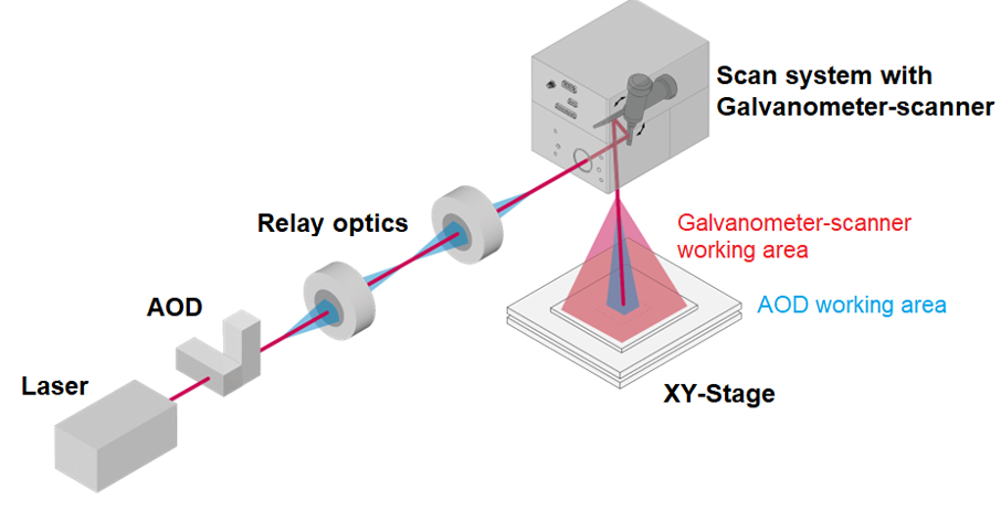
Several deflection units are placed in series in the optical path. Their angular contributions combine at the workpiece so that the final focal position depends on all deflection stages. The arrangement includes the following elements:
AOD X and AOD Y: two orthogonal deflectors, or a two-dimensional AOD arrangement, provide fast deflection along both axes.
Relay optics: these transfer the AOD’s angular deflection correctly to the galvanometer entrance while maintaining beam quality and aperture matching.
Galvanometer scanner: this covers the larger processing field.
Optional XY stage: for larger workpieces, the stage supplies long-range movement while the scanner and AOD handle local patterns and details.
Combining an AOD with the stage and galvanometer preserves large-area coverage while increasing local dynamic response, supporting speed, precision and process consistency over larger workpieces.
The arrangement can be understood as coarse and fine control. The scanner and optional XY stage provide global positioning and the main trajectory. The AOD adds fast local offsets, oscillations and corrections, shaping beam motion at higher bandwidth.
Why cascaded scanning can benefit laser processing
The combination brings the galvanometer’s flexible large-field positioning together with the AOD’s fast, inertia-free deflection, helping reconcile efficiency and quality in micromachining and precision manufacturing.
1. Higher effective bandwidth where the process needs it
A process may not need maximum bandwidth continuously, but it can need it at sharp marking corners, dense hatch patterns, rapid point-to-point drilling, high-frequency welding or texturing oscillations, and local motion used to manage heat accumulation or stabilise a melt pool. An AOD changes deflection quickly in these situations, allowing the galvanometer to remain in a stable operating range.
2. Contour fidelity and throughput in detailed geometries
Throughput in detailed vector processing is often limited by scanner settling and short-vector tracking. SCANLAB scanners can provide fast response, including sub-millisecond settling under suitable system and tuning conditions, and high writing speeds in marking configurations. Adding an AOD allows some very short or sharp motion to move into the local deflection layer, reducing tracking-error effects and improving energy uniformity while preserving processing speed and quality.
3. Additional process modes: oscillation, compensation and path shaping
The value of cascaded control extends beyond speed to greater control over the beam path:
Wobble: high-frequency oscillation can modify weld characteristics, enlarge the effective melt-pool interaction or generate controlled textures.
Dynamic trajectory compensation: local deflection can correct predictable errors associated with scanning delay and, where feedback is available, adjust for measured differences.
High-speed point placement: rapid deflection supports drilling and pixel-like patterns at rates beyond those available from a purely mechanical system.
Architecture using SCANLAB scanners and control
The architecture has optical, planning and real-time synchronisation layers. The laser first passes through a two-dimensional AOD, then relay optics transfer the beam to the galvanometer system before focusing on the workpiece. Software converts geometry and process inputs into an executable galvanometer macrotrajectory, then derives the AOD microtrajectory. Both deflection layers run on one time base so that position, laser emission and modulation remain coordinated.
1. Interfaces
SL2-100 is SCANLAB’s digital galvanometer-control interface and can return additional scanner parameters. In the cascaded architecture it provides a deterministic data connection: RTC commands travel to the scanner, while status and telemetry return for monitoring and diagnosis.
SCANLAB’s Ultra-Fast Pixel Mode, or UFPM, brings the AOD into RTC control. It can drive modulation and deflection at rates up to 3.2 MHz. This is faster than conventional galvanometer updating and supports high-frequency oscillation, dense point patterns and high-bandwidth compensation.
2. Synchronised execution
From the requested geometry and process parameters, the system coordinates the motion components and creates a laser job executable in the real-time control domain, synchronising the scanner, AOD and laser.
SCANmotionControl first plans the main scanner trajectory and, where used, the XY stage trajectory. It converts CAD or vector features and parameters such as processing speed, jumps, acceleration limits and timing constraints into achievable motion. Path smoothing and parameterisation, velocity, acceleration and jerk limits, and time-consistent setpoints allow the scanner to follow predictably within its dynamic limits. This macrotrajectory establishes global beam position versus time, the start and end of each segment and the timing windows for laser emission.
An Additional Planner then computes AOD micromotion, adding high-bandwidth XY oscillation, local corrections or feature sharpening while staying within the AOD’s deflection range and the macrotrajectory timeline. The RTC Slave executor combines motion and laser instructions and sends them through the RTC6 master–slave architecture. The master controls the scanner through SL2-100 and synchronises laser emission through the laser interface; slaves drive AOD XY through UFPM. SyncBus and its Trigger Slave mechanism align the AOD updates with scanner motion and laser emission. A Diagnosis module checks AOD travel and trajectory validity before execution and during commissioning to avoid saturation, clipping and edge nonlinearity.
Performance and test configuration
The described test system was installed in the Digital Photonic Production research laboratory. It combined an EdgeWave ultrashort-pulse laser, a BUSCH Microsystems XY stage and a SCANLAB excelliSCAN 14 with a 100 mm f-theta lens. A two-dimensional AOD was integrated into the optical path for fast, fine local control.
In that example, the AOD field was approximately 1.2 × 1.2 mm, the galvanometer field approximately 40 × 40 mm, and the stage coverage approximately 300 × 300 mm. The quoted maximum beam-positioning speeds were 2 × 10⁸ mm/s for the AOD, 9 × 10³ mm/s for the galvanometer and 1 × 10³ mm/s for the stage. These values depend on their definitions and test conditions. The key distinction is the allocation of tasks: very-high-bandwidth motion in a small AOD field, fast scanning over a medium field, and large-range stage movement and stitching. Cascading preserves coverage while adding rapid local motion.
Application examples
1. Wobble for hatch filling and shorter process time
In production, efficiency depends not only on long straight vectors but also on dense hatch lines, area coverage, uniform removal and texturing. A galvanometer working alone may require closely spaced lines and frequent reversals. Wobble can stabilise melting, shape weld geometry, manage overlap and heat input, and generate designed textures, making it relevant to welding, ablation and functional surfaces.
The cascaded arrangement lets the galvanometer follow the main path while the AOD supplies high-frequency local oscillation. Amplitude and frequency can change during processing, making wobble a process-shaping tool rather than simply a speed increase. This can improve energy uniformity and shorten processing while meeting surface or ablation requirements. At UFPM rates, the oscillation can extend beyond galvanometer-only performance and explore frequencies at which melt-pool or ablation physics respond differently.
In the illustrated test, changing hatch spacing from 300 µm to 1,500 µm while adjusting AOD oscillation amplitude reduced processing time by up to 70%. This is a result for the described process example.
2. Sharper corners and trajectory compensation
Corner quality affects sharpness, burrs and dimensional consistency in complex vectors. A scanner can round corners or overshoot at high speed, requiring slower motion or special strategies. An AOD can supply rapid local corrections while the main path remains smooth, improving conformity to the target contour in fine marking, microstructures and precision trimming.
The example compares AOD corner sharpening on a smooth constant-speed trajectory with skywriting and stop-and-go pulse-on-demand approaches, reporting a shorter cycle time for the AOD strategy.
The same principle can compensate a predicted scanner deviation under acceleration limits by adding a small AOD offset while RTC keeps laser pulses aligned with the path. For dense short vectors such as text, microstructures and sharp symbols, this can improve consistency and stability.
3. Dense point arrays and drilling
Point-to-point positioning and settling can limit drilling and point-array throughput. In a macropositioning and local-point-placement strategy, the scanner positions over an area and the AOD rapidly places points within its local field. Deterministic RTC triggering associates each pulse with the combined scanner and AOD position, reducing repeated settling and supporting dense microhole arrays or high-density textures.
4. Large-area micromachining
For extra-large work areas, the scanner and XY stage jointly provide coverage, with overall area governed mainly by stage travel. The stage performs large movements and stitching, the galvanometer scans medium-sized areas, and the AOD improves local detail, high-frequency wobble and compensation. Large-area coverage can therefore be combined with micromachining-quality local control.
Conclusion
Industrial use of a cascaded AOD-and-galvanometer system depends on synchronisation to a shared clock. The SCANLAB architecture addresses three requirements:
SL2-100 controls the galvanometer digitally and returns scanner parameters to RTC6 for monitoring and analysis.
RTC6 UFPM supports AOD modulation and deflection at rates up to 3.2 MHz.
SCANmotionControl supplies the macrotrajectory, converting geometry and process requirements into executable, time-consistent scanner motion and defining the global position-versus-time reference for AOD planning.
The resulting architecture combines large-field coverage with fast local control for adaptive wobble, faithful high-speed corners and dense drilling or point patterns. The described architecture is currently used for testing and demonstration. The research indicates application potential as control and synchronisation mature and the range of processes expands.